Hardware and GNSS/PPS wiring#
Why#
Two distinct signals come out of the GNSS receiver, and they don’t play the same role: the serial stream (NMEA/UBX) gives an approximate time with a variable latency of several tens of milliseconds, while the PPS (Pulse Per Second) pulse marks the exact tick of the second with precision on the order of tens of nanoseconds. Wiring both correctly, and understanding why both are needed, is the prerequisite for everything else.
Hardware needed#
| Component | Indicative reference | Role |
|---|---|---|
| SBC | Raspberry Pi 5 (4 or 8 GB) | Compute |
| GNSS receiver | u-blox NEO-M9N (UART + PPS) | Time reference |
| Antenna | active, SMA connector | Satellite signal reception |
| Antenna cable | 50 Ω coax, known length | Propagation delay ≈ 5 ns/meter, to compensate if possible in the GNSS receiver configuration |
| Storage | microSD A2 ≥ 32 GB, or SSD/NVMe | System; logs live in RAM (tmpfs) |
| Network | RJ45 | NTP/NTS, hardware timestamping |
| Cooling | PWM fan | Oscillator thermal stability |
Nothing more is strictly required for a working Stratum 1, no HAT, no user-facing I2C bus, no external display clock.
This server’s hardware#
The table above stays deliberately generic: any receiver exposing NMEA + PPS and any active SMA antenna will do. As an example, here are the exact models used on this server.
| Component | Exact model | Key points | Indicative price |
|---|---|---|---|
| SBC | Raspberry Pi 5, 8 GB | BCM2712 SoC (quad Cortex-A76 at 2.4 GHz), 40-pin GPIO, PHC on the network controller | ~ 80 € |
| GNSS receiver | SparkFun GPS Breakout NEO-M9N, ref. GPS-17285 | u-blox NEO-M9N with internal TCXO, 4 constellations, UART + PPS (timepulse), SMA connector | ~ 70 € |
| Antenna | u-blox ANN-MB-00 | active multi-band L1 + L2/E5, 28 dB LNA gain, 5 m cable, male SMA, magnetic base, IP67 | ~ 50 € |
| Enclosure | anidees extra-high aluminium (AI-PI5-SG-H) | passive dissipation through the aluminium, room for a HAT, airflow vents | ~ 30 € |
| Storage | SanDisk MAX ENDURANCE 32 GB microSD | high-endurance range built for continuous writing | ~ 20 € |
| RTC battery | Raspberry Pi RTC battery (rechargeable) | keeps the clock powered when off, trickle-charged by the Pi | ~ 5 € |
That is roughly ~ 250 € total, power supply and shipping excluded.
Three of these choices are not neutral for a time server:
- The ANN-MB-00 antenna is multi-band (L1/L2) while the NEO-M9N only uses the L1 band: backward compatibility applies, and what is really gained is robustness (IP67, magnetic base, 5 m cable) for mounting behind a window or outdoors, at no unreasonable extra cost. This antenna is not officially compatible with the L5 band.
- The aluminium enclosure dissipates passively, which helps pin the crystal’s thermal operating point (Thermal stabilization and From bare crystal to pseudo-TCXO chapters); the PWM fan adds to it.
- The MAX ENDURANCE card is sized for continuous writing: a complementary safety margin on top of the choice to keep logs in tmpfs (Filesystem chapter), which already reduces card wear.
Pick a GNSS receiver that exposes both a serial output (NMEA or UBX) and a separate hardware PPS pin. An “all-in-one” USB receiver without an exposed PPS will never reach microsecond-level precision: the USB port itself introduces several milliseconds of variable latency.
How: the wiring#
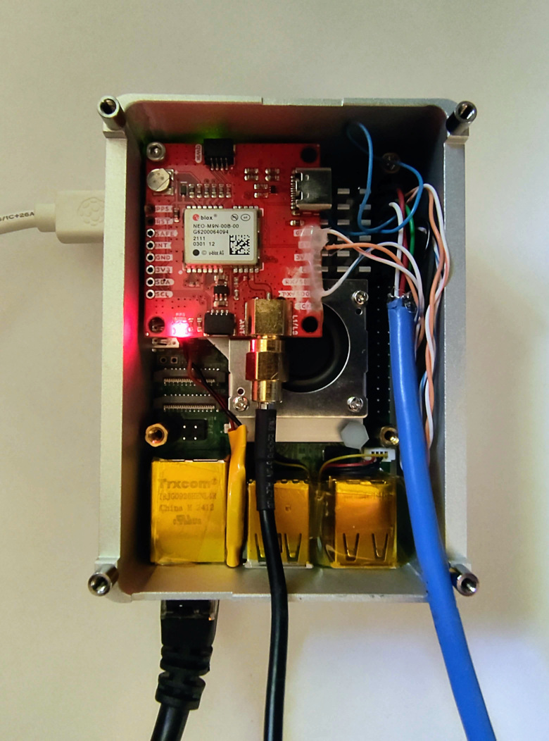
The diagram below details the connections visible in the photo.
┌──────────────────────┐                      ┌────────────────────────────────┐
│    u-blox NEO-M9N    │                      │         Raspberry Pi 5         │
│   (GNSS receiver)    │                      │        (GPIO, 40 pins)         │
│                      │                      │                                │
│                  TX  │─────────────────────►│ GPIO15 / RXD0 (ttyAMA0)        │
│                  RX  │◄─────────────────────│ GPIO14 / TXD0                  │
│                 PPS  │─────────────────────►│ GPIO4  (pps-gpio)              │
│                 GND  │──────────────────────│ GND                            │
│                 VCC  │◄─────────────────────│ 3V3                            │
│                      │                      │                                │
│ [SMA] active antenna │                      │                                │
└──────────────────────┘ └────────────────────────────────┘- TX/RX (UART,
ttyAMA0): carries NMEA/UBX frames (position, approximate date). This stream tells you which second just ticked. - PPS (GPIO 4): one electrical pulse per second, aligned to the rising edge of the UTC second. This is what gives you precision.
- 3.3 V power only, never 5 V: the Pi’s GPIO pins do not tolerate 5 V inputs.
The Linux kernel handles PPS via the pps-gpio module, which fires a
hardware interrupt (IRQ) on every rising edge and exposes the result as
/dev/pps0. This is covered in detail in the
GNSS/PPS acquisition chapter.
Pitfalls to avoid#
- Swapping TX and RX. Classic mistake: the receiver’s TX should go to
the Pi’s RX, not to its own TX. If
ttyAMA0receives nothing, check this first. - Antenna cable too long without compensation. Radio signal propagates
at ~5 ns/meter through coax cable. Over a few meters the effect is
negligible; beyond that, chrony lets you explicitly compensate for this
delay (
offsetdirective on the PPS refclock, see the Chrony chapter), but you need to measure the actual cable length first. - Poorly placed antenna. A GNSS antenna needs a clear view of the sky. Behind a window facing open sky works fine (that’s the actual production setup for this project); enclosed in a metal case or in a basement does not.
- Forgetting the RTC backup battery. If the Pi uses a battery-backed real-time clock, it must be connected before the first boot to benefit from automatic trickle charging, otherwise the clock resets on every power loss, which delays acquiring the first GNSS fix after reboot.
Verify#
Before installing any software, two physical checks are enough at this stage:
- Wiring continuity: using a multimeter, check for no short circuit between 3V3 and GND once the receiver is connected, before first power-up.
- Receiver power: once the Pi has booted (with a minimal OS, see next chapter), the GNSS receiver should show an activity LED (depending on model) as soon as it acquires satellites, typically tens of seconds to a few minutes on a cold start.
Full software verification (ppstest, gpspipe) is covered in the
GNSS/PPS acquisition chapter.
📚 Going further
- The PPS signal on modern u-blox receivers is aligned to the UTC second transition with ±10 to 30 ns precision (u-blox NEO-M9N manufacturer specifications).
- NMEA frame latency over serial (UART, 9600 baud) is on the order of ±10 ms, non-deterministic, as it depends on CPU load and UART buffering, which is structurally why PPS is required for any precision better than a millisecond. See Michael A. Lombardi et al. (NIST), Time and Frequency Measurements Using the Global Positioning System (GPS), 2001, on serial interface latency versus hardware PPS.
- The GPS L1 C/A navigation frame format (50 bit/s, 30 s frame) is specified in IS-GPS-200 (Interface Specification, latest revision N).
- Manufacturer documentation for this server’s hardware: NEO-M9N Data sheet (UBX-19014285) and its Integration manual (UBX-19014286, via the u-blox portal); antenna ANN-MB Data sheet (UBX-18049862) and Product summary (UBX-18047741); SparkFun board and its hookup guide.